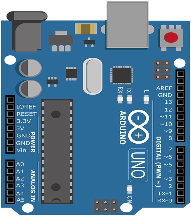
| LED |
It comes with built-in LED connected through pin 13. Providing HIGH/ LOW
value to the pin will turn it ON / OFF.
|
|
Vin
|
It is a 5V input / supply voltage pin to the Arduino Board through a USB
port. USB (5V), Vin
(7V to 20V) pin, or DC power jack are the 3 ways to provide the power for the
board. More voltage provided damages the board.
|
|
GND
|
Ground pins.
|
|
Reset
|
Used to the program running on the board.
|
|
PWM
|
Pins (3,5,6,9,10, 11) is provided by PWM which provides 8-bit output PWM.
SPI. It is known as Serial Peripheral Interface. Four pins 10(SS),
11(MOSI), 12(MISO), 13(SCK) provide SPI communication with the help of SPI
library.
|
|
AREF
|
Analog Reference (AREF) pin is used for providing a reference voltage to
the analog inputs.
|
|
TWI
|
A4, A5 pins are used for Two-wire Interface (TWI). TWI communication is
accessed through Wire Library.
|
|
Rx
|
It is used to receive data. i.e. used of Serial Communication.
|
|
TX
|
It is used to transmit data. i.e. used of Serial Communication
|
|
External Interrupts
|
Pins 2 and 3 are used for providing external interrupts by providing LOW
or changing value.
|